1. The significance of TSI system
With the continuous increase of large-scale units and the continuous expansion of capacity, and even the emergence of multiple 10 million MW units under construction and already built, the significance of TSI is even more important. The system of large-capacity units is complex, the monitoring range is large, and the projects are numerous. The operation and monitoring of operators must be replaced by a reliable safety monitoring system to reduce the possibility of misoperation. At the same time, for high-speed rotating precision machinery such as steam turbines, any mistakes will pay a heavy price. A qualified and reliable monitoring system can avoid misoperation and accidents and ensure the property safety of the large main engine such as steam turbines. The TSI system we are talking about today is about to come out.
TSI (Turbine Supervisory Instrument) is a steam turbine monitoring instrument system. It is a reliable multi-channel monitoring instrument that can continuously measure the mechanical operating parameters of the rotor and cylinder of the steam turbine-generator set, display the operating status of the machine, provide output signals to the signal instrument, and issue an alarm or even automatically shut down the steam turbine when the set operating limit is exceeded. In addition, TSI can also provide measurement signals for fault diagnosis and cooperate with other systems for fault analysis. (This article uses the SAIC NK600-24.2/566/566 600MW supercritical intermediate reheat two-cylinder two-row air-cooled condensing steam turbine as an example)
3.1. Bearing vibration
According to the relative position of the detection body, vibration can be divided into three types: absolute vibration of the shaft, absolute vibration of the bearing seat, and relative vibration of the shaft and the bearing seat. According to the principle of vibration, the axis trajectory can be obtained by synthesizing the vibration in the X and Y directions. There is no necessary internal connection between the vertical and horizontal directions of the shaft, that is, the vibration in the vertical direction (Y direction) is already very large, while the vibration in the horizontal direction (X direction) may be normal. Therefore, a probe is installed in each vertical and horizontal direction. Due to the influence of the horizontal center plane on the installation, in fact, the two probes can be installed perpendicular to each other. When the gap between the sensor end and the rotating shaft surface changes, the sensor outputs an AC signal to the plate, and the plate calculates the gap change (i.e. vibration) peak-to-peak (P-P) value.
In the measurement of shaft vibration, it has been explained that the vibration of the large shaft can be transmitted to the bearing shell. The speed sensor is used to measure the movement speed of the shell relative to the free space. The plate detects and integrates the speed signal from the sensor, converts it into a displacement value, and calculates the corresponding peak-to-peak position.

Vibration installation schematic diagram
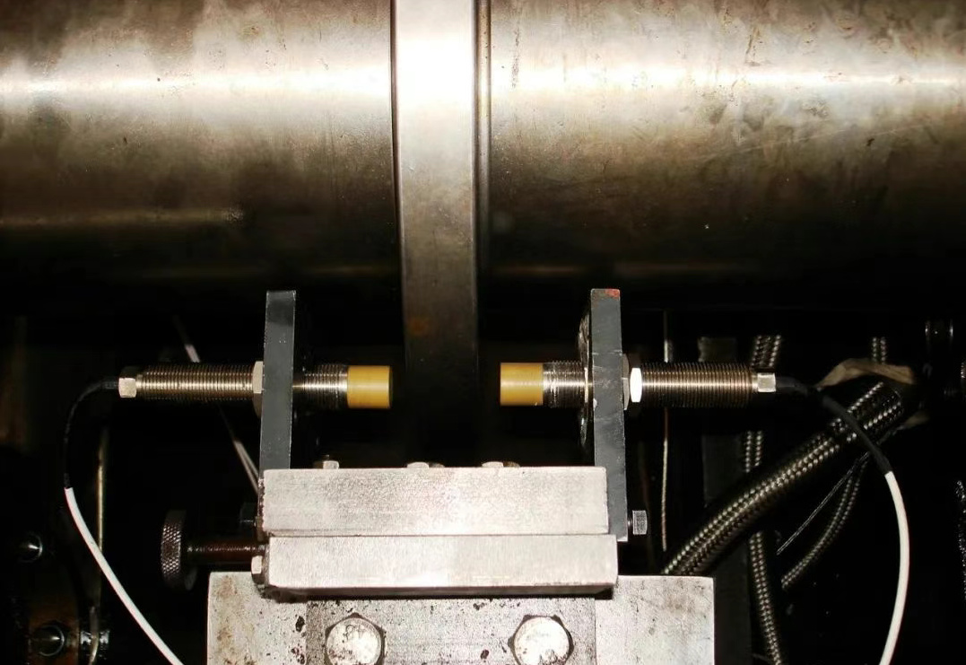
3.2, Axial displacementFour approach probes are usually used for measurement, installed at the thrust plate at 4 bearings. These four sensors are grouped in two and installed symmetrically to the rotor. The two sensors in each group are in an "and" relationship to ensure that no error signal is given when a channel fails. The results of the two groups of measurement sensors are independent of each other, that is, the "or" relationship, so as to effectively protect the safety of the steam turbine unit. The alarm value is ±0.9mm and the trip value is ±1.0mm.

Axial displacement installation diagram
Differential expansion is also called relative expansion. The purpose of monitoring differential expansion is to prevent possible friction between the rotor and the cylinder. The rotor expansion is greater than the cylinder expansion in the positive direction, and vice versa in the negative direction.
Differential expansion probes are divided into high-pressure differential expansion and low-pressure differential expansion. The high-pressure differential expansion has two probes, which are installed opposite to each other. The differential expansion signal value is calculated based on the voltage difference measured by the two probes; the low-pressure differential expansion is an LVDT type measuring device, which can directly measure the voltage and calculate the low-pressure differential expansion signal value. The high-pressure differential expansion alarm value is 9.5mm, and the trip value is 10.3mm; the low-pressure differential expansion alarm value is 15.2mm, and the trip value is 16mm.

Low-pressure differential expansion installation diagram
3.4. Absolute expansion of the cylinder
Cylinder expansion is also called the absolute expansion of the cylinder. In order to prevent jamming or dynamic and static friction accidents due to uneven heating of the cylinder, cylinder expansion must be monitored to ensure the safety of the unit.

3.5, eccentricity and key phase
Eccentricity is the bending of the shaft, that is, the radial position of the shaft. Under normal operation without internal and external loads on the shaft, the shaft will float in the designed position under the action of oil pressure damping. However, once the machine is subjected to a certain external or internal preload, the journal in the bearing will be eccentric, and its size is represented by the peak-to-peak value of the eccentricity, that is, the difference between the extreme values of the positive and negative directions of the shaft bending.
The so-called key phase device is to open a key slot on the shaft (or add a raised key), and then use an ordinary vibration probe to align the key. When the probe detects the key, the preamplifier outputs a pulse signal, and the period between two pulse signals is one turn. The key phase signal can also be used to indicate the phase of vibration. When the angle between the vibration probe and the key phase probe is known, the position of the unbalanced mass, that is, the position of the rotor high point, can be found. This is very important for the balance of the shaft.

3.6, turbine speed and zero speed
When the turbine rotates at high speed, if the torque and the reaction torque are unbalanced, the speed will change. When the speed is out of control, overspeed damage to parts will occur, and in severe cases, even a vicious accident of "flying car" will occur.
In order to ensure safety, the turbine speed must be strictly monitored. When the speed reaches the set value, an alarm is issued and protective measures are taken.
When zero speed occurs during shutdown, ensure that the gear is put into use in time.When the machine rotates, the top and bottom of the tooth of the gear plate pass through the probe, and the probe will periodically change the output signal, that is, the pulse signal. The board receives this pulse signal for counting and display, and after comparing it with the set value, it drives the relay contact output. Speed measurement range: 0~5000rpm; zero speed setting value, less than 1rpm.

4. Composition of TSI monitoring instrument
TSI monitoring instrument consists of sensor, preamplifier and monitor.

4.1. Sensor type, working principle and model
This article describes the eddy current sensor, acceleration sensor, linear differential transmitter and magnetoresistive sensor used in steam turbine.
4.1.1. Working principle of eddy current sensor
When a metal conductor is placed in a changing magnetic field, an induced current will be generated in the conductor. The streamline of this current closes itself in the metal body, which is usually called eddy current. The generation of eddy current must consume part of the magnetic field energy, thereby changing the impedance of the excitation coil. Eddy current sensors are made based on this eddy current effect.

4.1.2. Working principle of acceleration sensor
Speed sensor is suitable for measuring the vibration velocity and vibration displacement (after integration) of bearing seats, housings, etc.
The working principle is as follows: A permanent magnet is fixed on the sensor housing rigidly fixed on the object to be measured, and an inertial mass coil surrounds the magnet and is connected to the housing through a spring. During measurement, as the object to be measured vibrates, the magnet moves, causing it to generate magnetic field movement. The coil has a large inertial mass because it is fixed on the spring, that is, it is relatively stationary compared to an object with high-frequency vibration. In this way, the coil moves linearly in the magnetic field, generating an induced electromotive force, the magnitude of which is proportional to the linear velocity of the coil movement (i.e., the speed of the housing). By detecting the induced electromotive force, the linear velocity of the object to be measured can be obtained.
The magnetoresistive sensor is based on the working principle of magnetoresistive effect. Its core part uses a piece of special metal material, whose resistance value changes with the change of the external magnetic field, and the change or condition of the object is measured by the change of the external magnetic field. The magnetoresistive sensor has the characteristics of high precision, high sensitivity, high resolution, good stability and reliability, non-contact measurement and wide temperature range, and can perform dynamic and static measurements.
4.1.4, Sensor type and model
|
Monitoring project |
Sensor category |
Sensor + preamplifier |
Model installation quantity |
|
Shaft vibration |
Eddy current sensor |
TQ412+IQS452 | 14 |
|
Axial displacement |
Eddy current sensor |
TQ402+IQS452 | 4 |
|
Bearing vibration (1 watt) |
Acceleration sensor |
CA202+IPC704 | 1 |
|
Bearing vibration (2-7 watts) |
Acceleration sensor |
CE680 | 6 |
|
Eccentricity |
Eddy current sensor |
TQ402+IQS452 | 1 |
|
Key phase |
Eddy current sensor |
TQ402+IQS452 | 1 |
|
Speed |
Magnetoresistive sensor |
BEF1210 | 5 |
|
Zero speed |
Eddy current sensor |
TQ402+IQS452 | 1 |
|
High pressure differential expansion |
Eddy current sensor |
TQ403+IQS453 | 2 |
|
Cylinder expansion |
Eddy current sensor |
AE119 | 1 |
|
Module name |
Module model |
Number of modules |
|
CPU module |
CPU M | 1 |
|
Communication module |
MPC 4+IOC4T | 9 |
|
Power module |
PRS 6U | 2 |
|
Relay module |
RLC 16 | 1 |
 4.2.1, Overview of VM600 system cards
CPU-M: Communication gateway, used for local display, configuration and communication. Save all system configuration data, with local display (bar graph, digital display and engineering unit), and can display the real-time value of each channel. Provide flexible communication connection, RS-232/422/485 and Ethernet, support communication protocols such as TCP/IP and MODBUS, and provide high-speed data connection with the host computer running VM600 MPS or CMS software. Remember, hot swapping is not supported!
MPC4: 6-channel input module (4-channel input + 2-channel speed/key phase), used for machine monitoring and protection. One module can accept inputs from all sensors, including eddy current sensors, acceleration sensors, speed sensors, speed probes and other general sensors.
CMC16: 16-channel input for status monitoring. The first 4 channels can input key phase or other process signals, and the last 12 channels can input other process signals.
RPS6U: Power module. Provides 5V and ±12V power for the entire frame, and a redundant power module can be selected.

IOC-N: IO module for CPU-M, including network and communication.
IOC4T: IO module for MPC4, including sensor input, current output, buffer output and 4 relay alarm outputs. The alarm signal can be output to RLC16 or IRC4 through the bus.
IOC16T: IO module for CMC16, including signal input and output and communication connection.
RLC16 or IRC4 relay module: Both are relay output cards, the difference is that IRC4 is an intelligent relay output card, which can perform logical operations.

4.2.2、VM600 module status light description
Off: Configuration is not activated, channel is not running;
Red flashing: When dual channels are combined, the dangerous value is reached;
Yellow flashing: When dual channels are combined, the alarm value is reached;
Green flashing: Signal exceeds the limit, or disconnection;
Red: Channel reaches the dangerous value;
Yellow: Channel reaches the alarm value;
Green: Channel is running normally.
4.2.3、VM600 topology diagram
